Milestones
- Learning and Training Phase – Pre-Requisites for the start of operation:
- Configure The Correct Setting For The ESD.
- Prepare required generators for use.
- Ran a custody transfer print-out for official tank gauging.
- Connect Manifold Arm Spool Pieces.
- Opened required valves for line up.
- Assessment Phase – Operational flow and Assessment:
- Started cargo pumps on all tanks.
- Achieved required flow rate to shore.
- Staggering achieved for all tanks.
- The difference of 20cm achieved between CT1 and CT2.
- The difference of 20cm achieved between CT2 and CT3.
- The difference of 120cm achieved between CT3 and CT4.
Actions During Exercise:
- Deviation from Exercise:
- After starting or resuming discharging, do not open any non-required valves or close required valves. A caution message will be displayed to undo any incorrect actions. If not corrected, the exercise will be terminated.
- High Crossover Pressure:
- If the crossover pressure reaches 4 bar, the user will be warned to reduce the pump flowrate. If the pressure reaches 5 bar, the user must reduce the crossover pressure within 1 minute. Failure to do so will result in exercise termination.
- Not maintaining the required flowrate to shore:
- If the flow rate is not maintained between 11,500 m³/h and 12,500 m³/h after ramp-up, a caution alarm will be triggered, prompting the user to restore the flow within the required range. If the flow rate remains outside the limits and the alarm escalates to high priority, the exercise will be terminated.
- Emergency Shutdown During Operation:
-
- During the unloading process, an Emergency Shutdown may be triggered by the terminal.
In such a case, reset the ESDS system and associated machinery separately, then resume the discharging operation.
Note: When the HD compressor is reset, the surge valve will open, which may result in an incomplete lineup.
Alarms & Remarks
| Alarm Condition |
Alarm Time |
Alarm Level |
Alarm Title |
Alarm Description |
Actions |
|
|
Remark |
Obtained Level Difference Between CT1 and CT2 |
Obtained a 20 cm difference between CT1 and CT2. Now, the level difference can range between 35 and 45 cm. |
|
|
|
Remark |
Obtained Level Difference Between CT2 and CT3 |
Obtained a 20 cm difference between CT2 and CT3. Now, the level difference can range between 15 and 25 cm. |
|
|
|
Remark |
Obtained Level Difference Between CT4 and CT3 |
Obtained a 1.2 m difference between CT4 and CT3. Now, the level difference can range between 1.15 and 1.25m. |
|
|
|
caution |
In-proper Line Up For Discharging |
Proper line-up has to be done for discharging LNG to the shore. |
|
|
|
caution |
Open Master Valve And Close Return |
Open master valve CL107/207/307/407 and close return valve CL100/200/300/400 in CT1/2/3/4. |
|
|
|
caution |
Update CTS Report And Setup |
CTS Report and setup have to be updated before discharging LNG to the shore. |
|
|
|
remark |
Started Unloading |
Unloading of LNG has started, open master valves of remaining tanks and increase the discharge rate to the required level. |
|
|
|
caution |
Increase Flow Rate |
Maintain flow rate between -11500 and -12500. |
|
|
|
low |
High Cross Over Pressure |
High cross-over pressure in liquid line. |
|
|
|
caution |
Liquid Entering The Tank |
Liquid entering, close master and return valves when pumps are not running. |
|
|
|
caution |
Deviation Detected |
Deviation from the exercise is detected, undo your last action. |
|
Step By Step Procedure
- Learning and Training Phase – Pre-Requisites for the start of operation:
- Configure the ESD System
Navigate to the ESD System page and follow these steps:
- Set the Ship/Shore Link Selector switch to USE.
- Set the Pneumatic Selector switch to BYPASS.
- Set the ESD Port Selector switch to UNLOADING.
- Set the ESD Mode Selector to NORMAL.
Ensure the correct lights and indications are on, confirming the ESD system is ready.
- Prepare Generators for Use
Cargo pumps require at least three active generators.
To prepare the generators:
- Go to the PMS page via the side navigation bar.
- Turn on two of the three generators that are not currently running. (By default, one generator will already be on.)
- Run a CTS Report and Activate CTS Status for Official Tank Gauging
- Navigate to the CTS Main page using the side navigation.
- Set the Ship Mode to Harbour and Filter Mode to Normal.
- Fill in the required details in the report data section and select Loading in the CTS report setup.
- Connect Manifold Arms
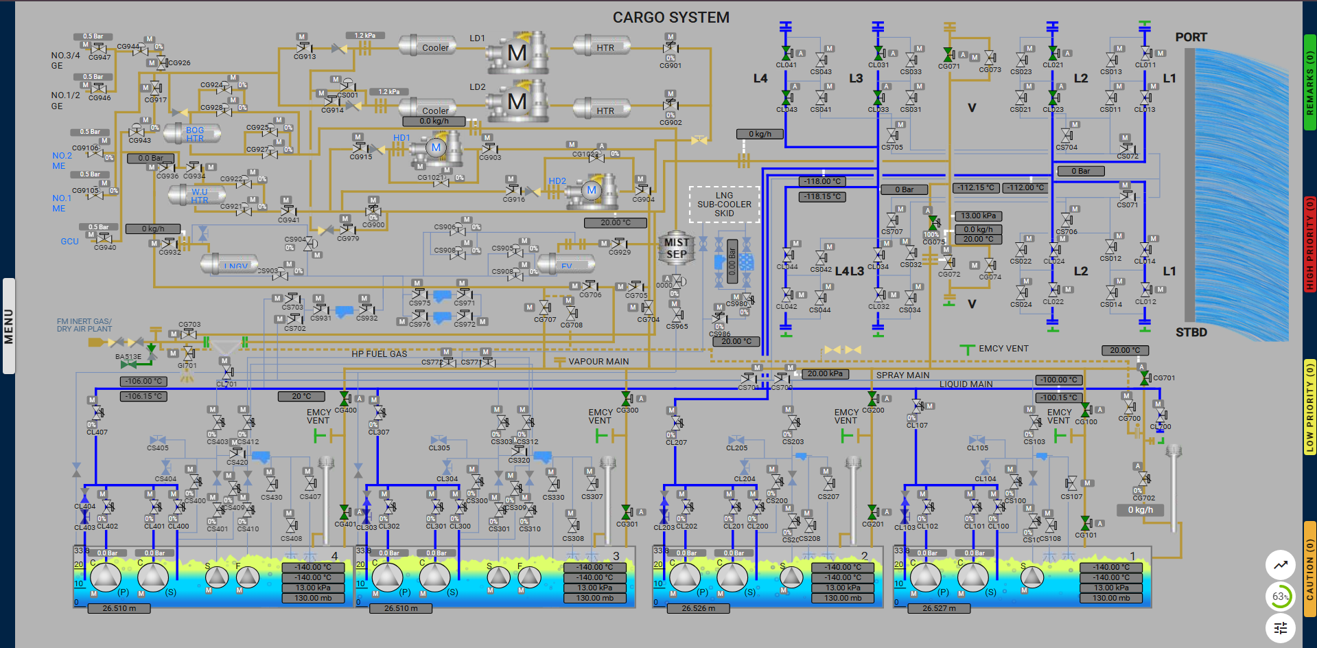
- Locate and connect the highlighted manifold arms positioned above the liquid manifold.
- Click on each arm to initiate the connection process.
- Complete Line-Up by Setting Valves
a) Set Cargo Liquid Manifold Valves:
-
-
- Open:
- No.2 Port Cargo Manifold Double Shut Valve: CL023
- No.3 Port Cargo Manifold Double Shut Valve: CL033
- No.4 Port Cargo Manifold Double Shut Valve: CL043
- No.2 Port Cargo Liquid Manifold ESD Valve: CL021
- No.3 Port Cargo Liquid Manifold ESD Valve: CL031
- No.4 Port Cargo Liquid Manifold ESD Valve: CL041
b) Set Vapour Line to No.1 Vent Mast:
-
- Open:
- Vapour Line to No.1 Vent Mast Valve: CG701
- Auto:
- No.1 Vent Mast Regulating Valve: CG702
c) Set Vapour Manifold Valves:
-
- Open:
- Vapour Line to Manifold Crossover Valve: CG075
- Port Vapour Manifold ESD Valve: CG071
d) Set Cargo Tank Vapour Valves:
-
- Open:
- No.1 Cargo Tank Vapour Valves: CG100, CG101
- No.2 Cargo Tank Vapour Valves: CG200, CG201
- No.3 Cargo Tank Vapour Valves: CG300, CG301
- No.4 Cargo Tank Vapour Valves: CG400, CG401
Ensure all valves are set to the correct positions for proper line-up. These valves can be opened from different pages in the system.
(Note: Valve CG702 is only available in the Cargo System page.)
- Assessment Phase – Operational flow and Assessment:
Important Note: When the HD compressor is reset, the surge valve will open, which may result in an incomplete lineup.
- Commence LNG Discharge to Shore by Running a Cargo Pump
- Navigate to the specific tank page by either clicking the pump icon on the unloading page or via the side navigation.
- Ensure the interlock conditions are met to start the pump.
- Once the interlock conditions are met, open the pump options by clicking the specific pump icon to start the pump.
- Note: After starting a pump, you cannot start another pump for the next 5 minutes.
- Increase and Maintain the Required Flowrate to Shore
After 55 minutes of unloading, the user will be alerted to increase and maintain the flowrate between 11,500 m³/h and 12,500 m³/h.
- If the flowrate is not increased within 5 minutes, a low-priority alarm will trigger.
- If the flowrate is still not adjusted after another 5 minutes, a high-priority alarm will trigger.
- If the flowrate is not adjusted within 1 minute after the high-priority alarm, the exercise will be terminated.
- Staggering Achieved for All Tanks
Achieve the required tank level differences:
- 8A: Achieve a 20cm difference between CT1 and CT2.
- 8B: Achieve a 20cm difference between CT2 and CT3.
- 8C: Achieve a 120cm difference between CT3 and CT4.
To achieve this, the user must adjust the pump discharge valves while monitoring the crossover pressure. If the crossover pressure is not maintained within the acceptable range, the exercise will be terminated.
Once the required tank differences are achieved, the exercise is completed.
Proper line up discharging ramp up and staggering: