Milestones
- Learning and Training Phase – Pre-Requisites for the start of operation:
- Configure the Correct Setting for the ESD.
- Start the Manifold Water Curtain.
- Prepare Gas Instruments for Use.
- Prepare LNG Vaporizer for Use.
- Connect Manifold Arm Spool Piece.
- Open Required Valves for Line-Up and Connect Spool Pieces.
- Assessment Phase – Operational flow and Assessment:
- Start Gassing-Up with Minimum Flow of 10m³/h.
- Achieve 40°C in LNG Vaporizer Outlet Temperature.
- Check All Gas Sampling Points.
- Monitor Vapour Outlet No.1 Vent.
Actions taken during the exercise
Deviation from Exercise
- After starting or resuming the cooldown, the user must not open any non-required valves or close any required valves. If this happens, a caution message will appear, instructing the user to undo the previous action.
- If the user fails to correct the action, the exercise will be terminated.
Not Maintaining the Inlet and Outlet Flow
- The user must ensure that the LNG vaporizer outlet flow and vapor to atmosphere flow are maintained between 11,500 m³/h and 12,500 m³/h.
- If the flow deviates from this range, alarms will be triggered, with a high-priority alarm issued if the issue persists.
- If the user cannot restore the flow, the exercise will be terminated within one minute.
Note: To maintain the LNG vaporizer outlet flow, adjust Valve CS903 in combination with the Flow from Shore and
to maintain the vapor-to-atmosphere flow, adjust Valve CG702 as needed.
Not Opening the Warm-Up Heater Bypass Valve
- During the initial phase of the exercise, the user will be prompted to open the outlet bypass valve of the LNG vaporizer.
- If the valve is not opened within 15 seconds, an LAHH alarm will be triggered.
- The user will have one minute to open the valve. If the valve is not opened in time, the exercise will be terminated.
Alarms & Remarks
| Alarm Condition |
Alarm Time |
Alarm Level |
Alarm Title |
Alarm Description |
Action |
|
|
remark |
Preparing Of LNG Vaporizer |
Usually, the LNG vaporizer is properly prepared 3 hours before the operation. |
|
|
|
remark |
Increase LNG Flow rate |
Vapor blocks might be there inside the lines, increasing the LNG flow rate from shore to 15 m³/h. |
|
|
|
remark |
Open LNG Vaporizer Bypass valve |
Open the LNG Vapourizer Bypass valve immediately. |
|
|
|
remark |
Open The Gas Detector |
Open the gas detector sampling point on the liquid line in any of the 4 tanks. |
|
|
|
remark |
Increase LNG Vaporizer Outlet Temperature |
Increase the outlet temperature of the LNG Vaporizer to 40°C. |
|
|
|
remark |
Valve CS904 To Auto Mode |
Set the valve output value to 40 and change the valve to auto mode. |
|
|
|
caution |
Maintain LNG Vaporizer Outlet Vapour |
Maintain the LNG vaporizer outlet vapor flow between 5000 kg/h to 6750 kg/h. |
|
|
|
caution |
Maintain LNG Vaporizer Flow And Vapour Flow To Atmosphere |
Maintain LNG vaporizer outlet flow and vapor flow to the atmosphere between 11500 kg/h to 12500 kg/h. |
|
|
|
caution |
Deviation Detected |
Deviation from the exercise is detected, undo your last action. |
|
Step-by-Step Procedure.
- Learning and Training Phase – Pre-Requisites for the start of operation:
1 – Configure the Correct Setting for the ESD
- Set the Ship/Shore Link Selector Switch to Use.
- Set the Pneumatic Selector Switch to Bypass.
- Set the ESD Port Selector Switch to Loading.
- Set the ESD Mode Switch to Normal.
2 – Start the Manifold Water Curtain
- To start the water curtain, go to the Miscellaneous Equipment page and activate either the bilge pumps or the fuel gas pumps. This will activate the water curtain.
3 – Prepare Gas Instruments for Use
- To start the gas instruments, go to the Miscellaneous Equipment page and activate the portable multi-gas detector by holding the power button for 5 seconds.
4 – Prepare LNG Vaporizer for Use
- Open both the inlet and outlet valves of the LNG vaporizer to prepare it for use.
5 – Connect Manifold Arm Spool Piece
- Locate the highlighted manifold arm positioned above the liquid manifold.
- Click on the highlighted arm to begin the connection process.
- Once all required arms are successfully connected, the milestone will be marked as completed.
6 – Open Required Valves for Line-Up and Connect Spool Pieces
Open the following valves:
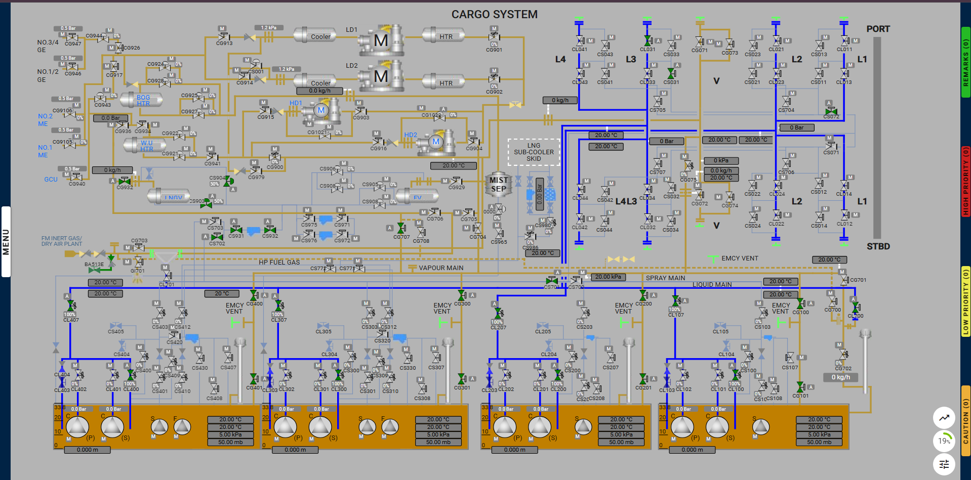
- CL031, CS031, CS072, CS701, CS702, CS931, CS932, CG932, CG707, CG100, CG101, CG200, CG201, CG300, CG301, CG400, CG401, CL107, CL207, CL307, CL407, CL100, CL200, CL300, CL400, CL700, CS903, CS904
And connect the spool piece below the valve CL700.
- Assessment Phase – Operational flow and Assessment:
7 – Start Gassing-Up with Minimum Flow of 10m³/h
8 – Achieve 40°C in LNG Vaporizer Outlet Temperature
- After the gassing-up process begins, the user will receive an alarm to reduce the outlet temperature.
- Decrease the temperature to 40°C.
9 – Check All Gas Sampling Points
- Navigate to the main tank pages and check all gas sampling points inside each tank to ensure they are functioning correctly.
10 – Monitor Vapour Outlet No.1 Vent
- Check the gas sampling point in the liquid line and verify the LNG vapor properties in the gas detector.
- Once the LNG vapor properties are visible on the gas detector, the exercise is complete.
Proper lineup for gassing up step 1: